SLUDGE HOPPERS
IN longitudinal tanks
The folklore1 in placing and sizing sludge hoppers
exceeds any expectation of the newcomers. "Oldcomers" know that the fight with
folklore in design of final clarifiers is endless, though successful2,3,4.
Nevertheless, folklorists are valuable. Without them science would be sometimes
boring.
In primary and in industrial settling tanks sludge hoppers
are correctly placed at the inlet end, just
below the inlet structure. The reason is obvious - heavy suspended solids sunk
straight into a relatively large hopper and do not have to be transported by
scrapers for a long distance. This approach and philosophy is wrong at
final clarifiers.
 |
 |
|
A hydraulic disaster if applied to final
clarifiers.
Correction of the excessive inlet energy was not invented by
renown engineers, researchers or professors but by plant operators at the Obersee WWTP (upper lake of Zurich, Switzerland), Josef Müller and Erwin Seliner in 1979.
http://www.musketeer.ch/sewage/ara_obersee.html |
Other locations of the hoppers
Placement of hoppers at the end of
the tanks reduces the adverse effects of excessive kinetic and potential energy.
The mid-length hopper design is a
method applied at very large clarifiers, where a single scraper cannot handle
the large area.
Design with two or more
hoppers is a quite irrational folklore and can be forgotten.
Scrapers
Both, non-metallic chain and flight scrapers and reciprocating
scrapers (http://www.nordicwater.com/en/index.cfm/product-groups/zickert)
safely handle an area of about 700 m2, though a few installations
were designed for area up to 1 000 m2 with a single chain and flight
scraper (for instance WWTP Salzburg, Austria -
ARA Siggerwiesen).
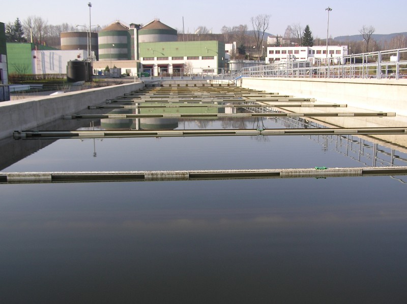
Typical references
|
|
Case A: Clarifiers 85 x 12 m. Combination of
con-current and counter-current
reciprocating sludge scraper system (ZICKERT).
No sludge hopper.
Excellent performance!
|

|
Case B: Clarifiers 60 x 12 m. Con-current
non-metallic chain and flight scraping system (DEWA).
No sludge hopper. Excellent performance!
|

|
Case C: Clarifiers 36 x 9 m. Con-current
non-metallic chain and flight scraping system (FINNCHAIN).
No sludge hopper. Excellent performance!
|
Theory
Theoretical approach is illustrated on the case C abolve. Old, shallow final clarifiers
were reconstructed to con-current non-metallic chain and flight
scraping system. Mathematical modeling of the sludge layer
for maximum design flow yields the figure below: Blanket concentration
vs. Height. The recycled sludge
concentration does not depend on the geometry of the clarifier but on the mass
balance around the clarifier only, see the chapter Definitions and Mass
Balance. Sludge layer above the recycled sludge uptake is more than 1
m high. A hopper would have no benefit because there is nothing to improve in
terms of sludge uptake. At the minimum design flow the sludge layer is of course
shallower but the influence on potentially fluctuating sludge uptake
concentration on the activated sludge system is negligible. At small flows
practically all sludge is in the anoxic/oxic tanks and minor fluctuation of the
recycled sludge concentration, even if exists, does not influence anything.
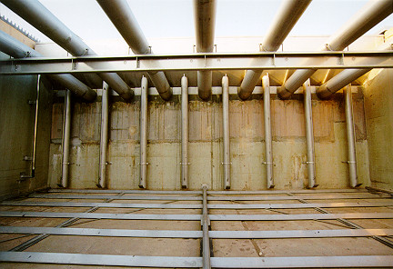
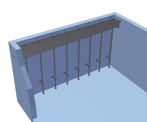
Sludge uptake in systems without hoppers requires an
appropriate arrangement, such as for instance Zickert
SIPHON or similar. Similarly, suction tubes manifolds have proved perfect.
 |
Mathematical modelling of sludge blanket
|
Parameter |
Symbol |
Value |
Units |
|
Feed concentration |
Xo |
3,1 |
g/l |
|
Underflow concentration |
Xr |
9,29 |
g/l |
|
Total flux |
Gt |
4,57 |
kg/m2
h |
|
Applied flux |
Ga |
3,05 |
kg/m2
h |
|
Average blanket concentration |
Xaver |
5,71 |
g/l |
|
Conjugate limiting concentration |
XL |
0,92 |
g/l |
|
Sludge blanket height |
SBH |
1,19 |
m |
|
Sludge detention time |
ThetaX |
1,49 |
h |
|
Sludge inventory |
MX |
1 996 |
kg |
|
In brief, at properly designed, up-to-date longitudinal tanks, sludge
hoppers depending on location, size etc. have
neutral or negative influence on
the clarifier hydraulics and increase
investment cost. Recycled sludge concentration does not depend on clarifier
geometry (including hoppers) but on mass balance around the clarifier.
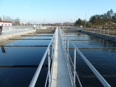
Practice
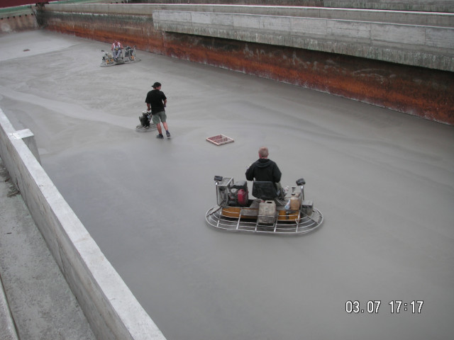
Reconstruction of a
large clarifier - no sludge hopper left.
Conclusions
Up-to-date, practically continuous con-current sludge scraping in sufficiently deep
clarifiers, together with sophisticated sludge uptake, does not need sludge
hoppers. Many installations in
several countries in last decade, generating crystal clear effluents, prove the theory, though
folklore and amateurism in design still survive.
1
Traditional customs, tales,
sayings, dances, or art forms preserved among people; an often unsupported
notion, story, or saying that is widely circulated (Merriam-Webster
Dictionary).
2
Dick Richard I.
(1976).
Folklore in the design of final settling tanks.
Journal Water Pollution Control Federation,
48,
pp. 633-644.
3
Parker D.
S., Kinnear D. J., and Wahlberg E. J.: Review of Folklore in Design and
Operation of Secondary Clarifiers. J. Environ. Eng. 127, 476 (2001).
4
Wahlberg Eric J.:
Folklore in Activated Sludge
Treatment Plant Operations.
Rocky
Mountain Water Environment Association 65th Annual Meeting, September 17, 2002.
